
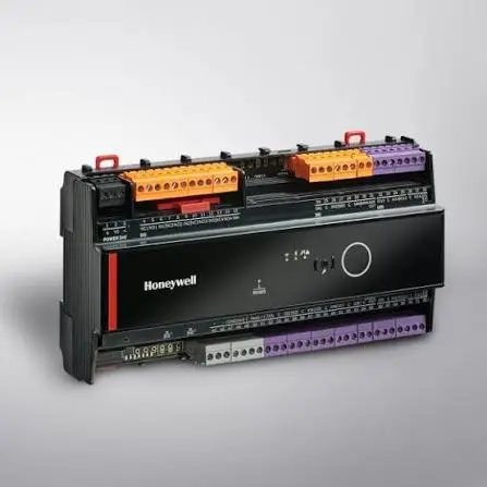
A building automation system is only as useful as the alarms it raises. When a Honeywell burner management controller trips into lockout, the code on the display is the difference between a five-minute reset and an unplanned shutdown that drags into hours. For facilities and maintenance teams running Honeywell 7800 Series relay modules, or any other Honeywell primary safety control tied into the wider BMS, knowing what a fault code actually means (and what it doesn’t) is a core competency, not a nice-to-have.
This guide breaks down how Honeywell BMS fault codes work, groups the most common Honeywell controller error codes by root cause, and lays out a decision process for when a reset is appropriate versus when a part needs to come off the subbase entirely.
How Honeywell Burner Controls Report Faults
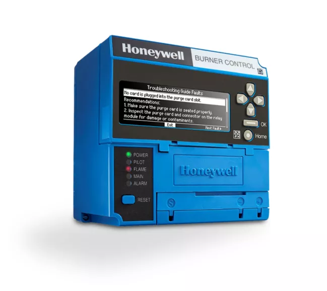
Honeywell 7800 Series relay modules (a family that spans the RM7800, RM7840, RM7890, RM7895, RM7897, and RM7838) sit at the safety-critical core of a burner management system. When the control detects a condition it isn’t allowed to ignore, it locks the burner out, closes an alarm contact, and stores a fault code identifying what tripped it.
Two things happen simultaneously:
- Visual annunciation. On a system fitted with an S7800 Keyboard Display Module (KDM), the code and its fault message appear on the screen along with the burner’s sequence status (STANDBY, PURGE, PILOT IGN, MAIN IGN, RUN, or POSTPURGE).
- Relay-level annunciation. On modules without a display, the same information is conveyed through LED patterns and first-out annunciation at the relay module itself.
Either way, the control isn’t just telling you that something went wrong. It’s telling you where in the sequence it went wrong, which narrows the troubleshooting field considerably before a technician ever picks up a meter.
What a Lockout Actually Means (and Why Resetting Twice Is a Bad Idea)
It’s worth pausing on this before diving into codes, because it’s the single most common mistake teams make with these systems: a lockout is not the problem. It’s the system correctly refusing to continue with a problem present.
Pressing reset clears the fault code and lets the burner attempt a fresh startup sequence. It does nothing to fix the underlying condition. If the same code reappears, that’s the control telling you the same thing twice, not a coincidence to reset past.
Repeatedly resetting after a flame failure is genuinely dangerous. Every failed ignition attempt puts a small amount of unburned fuel into the combustion chamber. Reset that cycle enough times without correcting the cause, and you’re building toward an explosive mixture. The correct workflow is:
- Reset once.
- Observe the full startup sequence.
- Note exactly where the failure recurs and which code the control reports.
- Diagnose before touching reset again.
Honeywell relay modules also retain a rolling history of the six most recent lockouts, each tagged with the cycle count and operating hour at which it occurred. That history is worth pulling before assuming a fault was a one-off; a code that has shown up three times in the last week is a different maintenance conversation than one that appeared once after a storm.
Never jumper an interlock, switch, or flame signal to keep a unit running through a fault. Flame safeguard diagnosis and repair should be handled by a qualified burner technician.
Honeywell 7800 Series Fault Code Reference Table
The table below covers the Honeywell BMS fault codes technicians run into most often on the 7800 Series relay module family (RM7800, RM7840, RM7890, RM7895, RM7897, RM7838). The display shows “LOCKOUT” followed by the number and message; the same numbers apply whether you’re reading them off an S7800 KDM or a first-out annunciator without a display.
| Code | Fault Message | What It Usually Means |
|---|---|---|
| 1 | No Purge Card | Purge card missing or not seated in its slot |
| 2–5 | AC Frequen/Noise, AC Line Dropout, AC Frequency, Low Line Voltage | Supply power outside spec: noise, dropout, wrong frequency, or low voltage |
| 6 | Purge Card Error | Purge card timing has drifted from its original reading |
| 7–9 | Flame Amplifier, Flame Amp/Shutr, Flame Detected | False flame: signal present when none should be |
| 10 | Pre-Ignition ILK | Pre-Ignition Interlock fault during STANDBY |
| 11–13 | Running ILK On, Lockout ILK On, Airflow Sw. On | An interlock or airflow switch was closed when it should have been open |
| 14 | High Fire Sw. | High Fire Switch didn’t close during PREPURGE |
| 15, 18 | Flame Detected | False flame during STANDBY or PREPURGE with shutter open |
| 16 | Flame-Out Timer | No pilot flame proven during the Pilot Flame Establishing Period |
| 17 | Main Flame Fail | Main flame lost during RUN after being proven for 10+ seconds |
| 19 | Main Flame Ign. | Flame lost during the Main Flame Establishing Period or first 10 seconds of RUN |
| 20 | Low Fire Sw. Off | Low Fire Switch didn’t close during PREPURGE |
| 21–23 | Running ILK, Lockout ILK, Airflow Switch | Interlock or airflow fault during PREPURGE |
| 24–25 | Call Service | Internal flame interlock in the wrong state (usually noise on the F lead) |
| 26 | Man-Open Sw. Off | Manual Open Valve Switch not closed when expected |
| 27 | Start Switch On | Start Switch energized during PREPURGE |
| 28 | Pilot Flame Fail | Pilot failed to ignite |
| 29–30 | Lockout ILK, Running ILK | Interlock fault, including the airflow switch |
| 31 | Low Fire Sw. Off | Low Fire Switch didn’t close during RUN |
| 32 | Airflow Switch | Combustion airflow interlock fault; suffix letter identifies the specific switch on Expanded Annunciator systems |
| 33 | Pre-Ignition ILK | Pre-Ignition Interlock fault; fuel valve must close within 5 seconds |
| 34 | Control On | Control input energized at the wrong time (field wiring error) |
| 35–40 | Call Service | Internal output check failure on the safety relay, main valve, pilot valve, or ignition terminal |
| 41–44, 48–49 | Main Valve On, Pilot Valve On, Ignition On, Pilot Valve 2 On, Delayed MV On, Man-Open Sw. On | Explosion hazard: a valve or ignition terminal is powered when it should be off. Remove power and fuel supply immediately |
| 45 | Low Fire Sw. Off | Low Fire Switch failed to close or hold closed |
| 46 | Flame Amp Type | Wrong or incompatible flame amplifier installed |
| 47, 50 | Jumpers Changed, Jumpers Wrong | Configuration jumpers don’t match the startup sample, or an illegal jumper combination is present |
| 51 | Flame Too Strong | Flame signal too high to be valid; usually a shorted lead or failing amplifier |
| 52–53 | Call Service, Lockout Switch | Pilot Valve 2 or lockout input fault |
| 54–58 | Comb. Pressure, Purge Fan, Block Intake | Combustion pressure, purge fan, or intake faults (Fulton pulse models) |
| 61–66 | MV1/MV2 Off/On, VPS Off/On | Main valve or Valve Proving Switch in the wrong state |
| 67 | AC Phase | L1 and L2 miswired or swapped |
| 68 | Pre-Ignition ILK | Pre-Ignition Interlock fault |
| 71–75 | Device specific | Firing rate motor, special function input, or flame feedback faults on specific models |
| 76–93 | Accessory Fault | Expanded Annunciator or terminal programming conflicts |
| 94–107 | Call Service | Internal relay module self-test or flame signal crosscheck failure |
| 108 | Call Service | Lost memory or unprogrammed device |
| 109 | Call Service | Negative cycle test failed: missing earth ground or incorrect line phasing |
| 110 | Call Service | Configuration jumpers don’t match stored values. If changed after 200 hours of operation, this is a permanent lockout and the module must be replaced |
| 111–127 | Call Service | Relay module self-test or safety relay feedback failure |
Codes 41, 42, 43, 44, 48, and 49 carry an explicit explosion hazard warning in Honeywell’s documentation. Don’t treat these as a routine reset: de-energize the system, shut off the fuel supply, find the wiring fault, and only restore fuel once it’s corrected.
For a fault not listed here, or one that returns immediately after every reset, that’s a signal to escalate to a qualified burner technician rather than continue cycling the reset button.
The Four Fault Families Behind Most Service Calls
Honeywell 7800 Series controls report up to 127 distinct diagnostic codes, but in practice, the overwhelming majority of service calls trace back to four categories. Understanding these clusters is more useful day-to-day than memorizing the full code table.
1. Flame Failure: Pilot or Main Won’t Prove
This covers codes where no flame was established at all (during the Pilot Flame Establishing Period or the Main Flame Establishing Period) as well as codes where a flame that had already proven was lost mid-run.
Where to start:
- Read the flame signal on the KDM during a supervised trial. A signal sitting near or below the 1.25 Vdc minimum points at a detection problem before any valve or gas train component gets touched.
- Inspect the scanner or flame rod. Clean the UV lens, rule out moisture inside the scanner conduit, and confirm the sighting is actually aimed into the flame envelope. A scanner that reads the pilot fine at low fire but loses the main flame at high fire is almost always a sighting issue, not an electrical one.
- Verify pilot gas pressure, main fuel pressure, and valve operation. Run a pilot turndown test after any pilot adjustment to confirm the flame holds at minimum size.
- Check the ignition transformer and electrode gap.
- Confirm the flame amplifier matches the detector type (UV, UV self-check, infrared, or flame rod) and is properly seated. If the signal still won’t come into spec, the amplifier gets replaced first, then the detector.
2. False Flame: The Control Sees Fire That Isn’t There
This is the opposite failure mode. The safeguard senses flame during a period when none should be present, and locks out to prevent fuel from entering a chamber it believes is already burning.
Where to start:
- Physically confirm there’s no flame or glowing refractory in the chamber. Hot refractory alone can hold a UV scanner “on.”
- Check for ignition noise coupling into the flame detector leads. The F and G leadwires need their own dedicated conduit, kept away from ignition and line-voltage wiring.
- Reseat the flame amplifier. A degrading amplifier that reports flame continuously will reproduce this fault on every single cycle.
- A signal reading as “too strong to be valid” usually points to a shorted detector lead or a failing amplifier rather than an actual flame condition.
3. Interlock and Airflow Faults
The running interlock string, which includes the airflow proving switch, either opened when it shouldn’t have or stayed closed when it should have opened. Honeywell’s codes distinguish between these two directions, but the diagnostic path overlaps heavily.
Where to start:
- Confirm the combustion air fan is actually running and that the intake and proving line are unobstructed. A plugged sensing line is by far the most common airflow switch failure.
- Verify the interlock string closes at the right point in the sequence by measuring for line voltage at the relevant terminal during PREPURGE. Voltage present means the string has closed; absent means a switch somewhere in the chain hasn’t.
- If an Expanded Annunciator is installed, it identifies the specific switch that opened first, so diagnose that switch rather than working through the whole string blind.
- The reverse fault, where an interlock was closed when it should have been open, usually means a welded, jumpered, or physically stuck switch. Find it and replace it. Never leave a jumpered interlock in service, even temporarily.
4. AC Power Quality
The relay module continuously monitors its own supply and will lock out on dropout, low voltage, frequency error, or excessive line noise.
Where to start:
- Measure line voltage at the module under load, not at idle.
- Rule out neutral and earth ground issues. A separate internal fault code (109 on the 7800 Series) points in the same direction and is worth checking alongside a recurring power-quality fault.
- If the same power-quality code keeps returning on an otherwise stable line, suspect a shared circuit or a failing upstream transformer before assuming the module itself is bad.
Resetting vs. Replacing: How to Tell the Difference
Not every fault code is a wiring problem, and not every fault code is a hardware failure. The 7800 Series is built as a modular system: the field wiring lands on a Q7800 subbase, and every active component (the relay module, flame amplifier, purge card, and KDM) plugs into it independently. That modularity is what makes hardware diagnosis fast, once you know which component a given code is pointing at.
As a general rule:
- Internal self-test and output-check faults (the kind labeled “Call Service” rather than tied to a specific field device) point at the relay module itself. Honeywell’s own guidance for most of these is consistent: reset once, and if the fault returns, replace the module.
- One code carries a hard rule worth flagging on its own. If the configuration jumpers are changed after the module has logged 200 hours of operation, it triggers a permanent lockout. That module cannot be reset back into service; it has to be replaced.
- Flame amplifier faults point at the amplifier first. It’s a plug-in component that swaps in seconds, but it has to match the connected detector type exactly.
- Persistent low or unsteady flame signal, once the amplifier has been ruled out, points at the scanner or flame rod. UV tubes lose sensitivity gradually with age, so a marginal signal today is often a lockout next month.
- Purge timing faults point at the purge card, another simple plug-in swap, provided the replacement carries the same timing designation as the original.
- A scrambled or blank display is a KDM or connection issue, not a safety lockout. The display isn’t part of the safety chain, and the burner will continue to run without it. Reseat or replace the KDM and reset.
Building Fault Response Into Your Maintenance Workflow
Reading a code correctly is only half the job. The other half is making sure the diagnosis, the parts swapped, and the recurrence pattern actually get logged somewhere your team can reference later, rather than living in one technician’s memory. A control that throws the same interlock fault every six weeks isn’t giving you six unrelated incidents. It’s giving you one root cause that hasn’t been fixed yet, and that pattern is only visible if the fault history, the corrective action taken, and the parts used are captured consistently across work orders.
That’s exactly the kind of pattern recognition a computerized maintenance management system is built for, and it’s where a properly configured CMMS earns its keep on equipment as safety-critical as burner management controls.
Facilities Management System Support From FacilityBot
Recurring BMS and burner controller faults are rarely just an electrical problem. They’re a maintenance data problem. FacilityBot is a cloud based CMMS software platform built to give facilities teams a single system of record for exactly this kind of recurring diagnostic work: log the fault code, the corrective action, and the part replaced against the asset, and the pattern surfaces automatically instead of getting lost across paper logs or individual technicians’ memory. As part of a wider facilities management system, FacilityBot ties fault history to preventive maintenance scheduling, so a burner control that’s trending toward hardware replacement gets flagged before it causes an unplanned shutdown, not after. For teams managing BMS-connected equipment across multiple sites, FacilityBot’s facilities management solutions bring work order tracking, asset history, and technician accountability into one platform, making it easier to tell the difference between a wiring fix and a part that genuinely needs replacing.
